Programmable digital readout for 3 or 4 axes
 The ACU-RITE DRO 300 is a versatile digital readout designed primarily for milling, drilling, boring, and lathe machines with up to four axes. A separate I/O unit provides switching input/outputs for simple tasks in automation.
Design
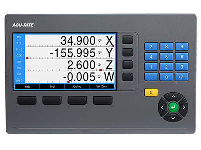
Thanks to its splash-proof full-travel keyboard, the DRO 300 is exceptionally well-suited for use in a workshop. It supports all operations with intuitive interactive menus on its large, easy-to-read colour flat-panel display.
Functions
The DRO 300 has the same functions as the DRO 203.
In addition, the DRO 300 offers a connection for the KT 130 edge finder. This allows you to define presets and datums with speed and precision. The DRO 300 digital readout supports you with special probing functions.
In addition, the DRO 300 is programmable, which makes it ideal for small-batch production on conventional machine tools. The DRO 300 allows you to store up to eight programs, each with up to 250 working steps. Programs are created by either keying them in step by step or by generating them using actual position capture (teach-in programming).
Data Interfaces
A USB port enables the writing and reading out of data and files.
Specifications
| Axes | 3 or 4; various axis designations |
| Encoder inputs | TTL |
| Display step1) | Adjustable, max. 7 digits Linear axis: 1 mm to 0.0001 mm Angular axis: 1° to 0.001° (00° 00′ 01”) |
| Display | 7″ TFT color screen (15:9); resolution 800 x 400 pixels for position values and dialog |
| Status display | TTool, reference point, operating function, feed rate, ABS/INC, mm/inch, stopwatch |
| Axis display | Switchable between DRO1 and DRO2 |
| Functions |
|
| For milling/drilling/boring |
|
| For turning |
|
| Programming | 8 programs with up to 250 steps |
| Error compensation |
|
| Data interface | USB connection, Type C |
| Switching I/O |
|
| Accessories | Stand, holder for mounting arm, protective cover, KT 130 edge finder (for milling) |
| Power connection | AC 100 V (–10 %) to 240 V (+5 %), 50 Hz to 60 Hz (±5 %), 33 W |
| Operating temperature | 0 °C to 45 °C (storage temperature –20 °C to 70 °C) |
| Protection |
EN 60 529 IP 40; front panel IP 54 |
| Mass |
1.7 kg |
| 1) Depends on the signal period of the connected encoder |
Documentation
Please note that only the products that are listed on this website are available for purchase in the United Kingdom.